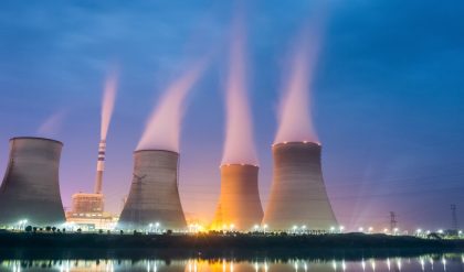
Typical diagram of a coal-fired thermal power station
| 1. Cooling tower | 10. Steam Control valve | 19. Superheater |
| 2. Cooling water pump | 11. High pressure steam turbine | 20. Forced draught (draft) fan |
| 3. transmission line (3-phase) | 12. Deaerator | 21. Reheater |
| 4. Step-up transformer (3-phase) | 13. Feedwater heater | 22. Combustion air intake |
| 5. Electrical generator (3-phase) | 14. Coal conveyor | 23. Economiser |
| 6. Low pressure steam turbine | 15. Coal hopper | 24. Air preheater |
| 7. Condensate pump | 16. Coal pulverizer | 25. Precipitator |
| 8. Surface condenser | 17. Boiler steam drum | 26. Induced draught (draft) fan |
| 9. Intermediate pressure steam turbine | 18. Bottom ash hopper | 27. Flue gas stack |


